Literature and Knowledge Center
In-depth information on Kingsbury products, technologies and applications.
Kingsbury Design Features in Lubrication, Setting Clearance
Since 1912, Kingsbury has gained unequaled experience in designing and manufacturing thrust bearings. This section details design features which we developed to improve your machine's performance.
Lubrication
For Kingsbury thrust bearings to operate safely and efficiently, continuous self-renewing oil films must be present between the shoes and collar.
The oil supplied to the bearing should be cooled and filtered, so that the average particle size is less than the bearing's minimum film thickness. The typical oil flow path is shown below.
End Play
To understand end play, or axial clearance, picture a double thrust bearing (one on each side of the collar). End play is the distance the thrust collar can be moved between the bearings during installation while applying load to either bearing.
Note: End play isn't an exact dimension. The shaft's maximum end play is limited to the smallest clearance between the stationary and rotating machine elements, while the shaft's minimum end play must be sufficient to prevent excessive power loss in the unloaded thrust bearing.
Any time a double thrust bearing is installed, end play must be provided to allow for an oil film to form in each bearing, and thermal expansion of the bearing elements.
Design Option: Normal thrust bearing overall height tolerances are about ±0.04" (1.0mm). To obtain suitable end play, filler plates, machined to adjust for the tolerances of the thrust bearing and bearing housing, should be installed. If it isn't practical to use filler pieces in the bearing assembly, thrust bearings can be provided with height tolerances of ±0.005" (0.13mm) on special order.
 |
|
| Fig. 1: Typical Oil Flow Path |
Setting End Play
Filler plates (or shims) are used most often to set both end play and the axial position of the rotating elements. To determine how thick the filler pieces should be, use the figure below and this equation for a double thrust bearing application:
BC = F1 + H1 + X + EP + H2 + F2 or
F1 + F2 + BC - (H1 + H2+ X + EP)
Important: While the total filler dimension (F1 + F2) is easily determined, the individual thickness dimensions F1 and F2 must be selected to position the shaft collar for proper spacing of the stationary and rotating machine elements. Remember that the operating film thickness of the loaded bearing will be much less than that of the unloaded bearing, causing the collar centerline to shift toward the loaded bearing during operation.
Design Tip: Allow for a slight, permanent set in the bearing elements by specifying a plus or a minus range for end play.

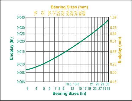
Fig. 2: Recommended Nominal End Play
 |
*The stacked height of any style thrust bearing can be accurately determined in four easy steps:
|
| Fig. 3: Setting End Play |


